News
17 Jan 2020
GAINING INSIGHT INTO CALIBRATION

Subscribe to CX E-News
GAINING INSIGHT INTO CALIBRATION
Calibration and gain structure are two of the least appealing concepts in audio, and arguably the least understood. Yet ironically, both are inextricably linked to the recording process. Most enthusiastic engineers, however, tend to run for the exit at the very mention of either of these concepts, in part because they’re dull (the topics, I mean) and also because they’re confusing.
But if you call yourself a recording engineer (or any variation on that theme) you simply must have some grasp of the principles underpinning both. Once you get a handle on them, your recordings will improve in myriad ways and you’ll be twice the engineer you were beforehand.
I’ve probably chosen the most boring (and enormous) topic in pro audio as the subject of this month’s Listen Here (and that’s really saying something!). But the reason is simple: the calibration of a recording system, particularly a digital one, and the gain structures you subsequently drive through it, are fundamental to the sound of your recordings.
If that all sounds like bollocks, let me explain. (And if you want to turn the page now, I’ll understand).
Focussing mainly on digital recording systems – because, let’s face it, the vast majority of systems these days are digital – let’s consider this format’s limitations.
We have a lot to cover here in a short time, so let’s dive straight in…
Calibrating Digital Systems
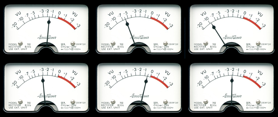
If you haven’t done it already, you need to get a grip on how your digital system reflects 0VU on an analogue meter, both on input and output. Why? Because even if your recording/mixing system is wholly digital, chances are you still have mics that record real sounds in the real world, and maybe an analogue monitor controller and speakers, in which case you’re also still squarely in the analogue domain.
How these two systems function together as one in your studio is mostly about how they’re calibrated.
It’s right at this early juncture that most people glaze over…So to clear up any confusion that might have already arisen, let me say this: in the analogue domain, all manufactured equipment has a ‘sweet spot’.
You’ve heard that term, right? What this generally means is that a pro audio unit’s analogue circuitry – whether it’s a compressor or a preamp or a reverb unit – is optimised to pass an electrical signal through it at 0VU (+4dBu), with the least amount of distortion and the least amount of noise.
Drive your audio signal too high above this and you’ll drive the analogue circuit into distortion; go too low and your sound will be dropping into its noise floor. Pretty simple.
Now right here, as an engineer, you might say: “Well, yeah, but analogue distortion is cool… it’s actually exactly what I’m after!” Yep, most of us would agree with that, depending on what we’re recording.
So now this is where calibration and gain structure marry together conceptually. If the digital converters of your recording system aren’t calibrated correctly (if they ever were) with your analogue equipment, they may ‘clip’ before you get the desired analogue distortion you’re after, and that’s not good.
Conversely, you might be an engineer who prefers pristine, distortion-free audio recordings, but still find yourself driving all your analogue chains into severe distortion in a vain attempt to record healthy (read ‘hot’) and clean digital signals. That’s not good either.
So what do you do, and how do we accommodate these two disparate recording preferences in one digital setup? Well, let’s back this conversation up a bit and try to clear up a few persistent myths.
Headroom vs Head Injury
As many of you know, analogue circuits have a thing called ‘headroom’ – some more than others.
What this term means, simply put, is this: above their 0VU (+4dBu) ‘sweet spot’ there’s some leeway in the analogue circuitry to accommodate signals that push higher than this ideal value. And because most audio signals are dynamic (varying in level to some degree) we need this headroom to function, particularly when we’re recording.
If the sweet spot of an analogue circuit is too small it becomes almost impossible to work with, so good gear generally has plenty of it (often between +20 and +30dBu).
Equipment such as analogue consoles, in particular, which have the difficult task of mixing lots of signals together, also have facilities onboard like EQ that can potentially boost levels dramatically. (If you didn’t have headroom in a console, the moment you boosted a signal it would distort!)
So if you’re recording an analogue chain into a digital system – like most of us are – you need to know what level your digital converter is receiving at this magical 0VU (+4dBu) analogue value.
Now conceptually, things can get very messy here very quickly, so I’ll try to keep it simple. In a nutshell, digital signal paths have no ‘headroom’ as such. None. Not because they’re sub-par, mind you, but because the concept simply doesn’t apply to them.
Instead, digital recorders have a dynamic range directly related to the size of the bit rate at which you’re recording, and a so-called ‘ceiling’ of 0dBFS (the FS stands for ‘Full Scale’).
Above this value, there’s nothing, simply because there’s actually no such thing as ‘above’ in a digital signal! That’s why I hate the term ‘ceiling’, because it infers that there’s something above it, but in this case that’s dead wrong… a myth.
Exceeding 0dBFS is like exiting the Earth’s atmosphere without a space suit.
Unlike the analogue domain where there’s space above (and below) the so-called ‘sweet spot’, digitally, there’s nothing because the concept of ‘above’ is meaningless. That’s why the moment you go ‘over’ (another misnomer) 0dBFS, you clip the digital input (or output) and get brutal, wholly unpleasant distortion.
It’s all very confusing, I know, so let’s persist with our explanation.
To avoid this clipping – and we really want to avoid it – we need to create some headroom in our digital recording system artificially, which we can do quite easily, albeit, arbitrarily. This will give us a sense of ‘above-ness’ and ‘below-ness’ to satisfy our tiny minds, even though the concept doesn’t really exist.
A Line In The Digital Sand
We simply pick an arbitrary value – typically between –16 and –20dBFS – and nominate this as our new 0VU level in our DAW.
For the purposes of this exercise, let’s call our 0VU analogue input level our new –20dBFS calibrated input level (an accepted international standard across the Film Industry). So now, when the final output VU meter of any of our recording chains measures 0VU, at our digital converter (and DAW metering) it will measure a calibrated value of –20dBFS.
By inference, all our cleanest, quietest and least noise-affected analogue RMS signals will now be recorded at around this level, giving us 20dB of newly created ‘headroom’, as if by magic.
Now, if we want heaps of distortion in our analogue front end, we can push all that gear harder in various ways without threatening to ‘clip’ our digital converter’s inputs.
We’ll still need analogue compressors and limiters in the signal chains, of course, to protect us from the horrors of our edge-of-atmosphere 0dBFS value, but if you want distortion chances are you’re already using these dynamics controls anyway to some degree to create that sound in the first place.
If, on the other hand, your recording preference is for clean, quiet and distortion-free digital recordings, you must first ensure that you optimise your analogue chains to measure an RMS value of around 0VU (+4dBu) throughout, which will then give you (at 24-bit, in your newly-calibrated digital system) a very healthy recording level of –20dBFS.
This calibrated recording chain has a two-fold benefit: it gives you a healthy signal with plenty of artificially prescribed so-called ‘headroom’, and also a decent amount of ‘above-ness’ for applying plug-ins during mixing, without it overloading the digital stereo output later.
Above-Ness? What The?
Now I know some of these terms aren’t exactly scientific, but hopefully they elucidate my point. In the analogue domain there’s a clean mid-point (if you like) that puts your sounds in focus like a clear lens. Above and below this focal point things get fuzzy.
But unfortunately the digital domain doesn’t work like this, so to accommodate the needs of the analogue domain, we must draw this digital line in the sand.
There’s far more to this topic than I can tackle in such a small space, unfortunately, and I’ve barely talked about gain structure at all, so next issue I may pursue this topic further (to bore you anew).
Meanwhile, if this article has raised more questions in your mind than I have managed to resolve, feel free to email me. The important first step is to face calibration and gain structure head on, even if you make a meal of it at first.
Once things clear up in your head, you’ll pop out the other side in far more control of the recording process than you were before.
Good luck!
Andy Stewart owns and operates The Mill on Victoria’s Bass Coast. He’s a highly credentialed producer/engineer who’s seen it all in studios for the last three decades. He’s happy to respond to any pleas for recording or mixing help… contact him at: andy@themill.net.au
CX Magazine – Dec 2019 Entertainment technology news and issues for Australia and New Zealand – in print and free online www.cxnetwork.com.au
© CX Media
Lead image via Wikipedia
Subscribe
Published monthly since 1991, our famous AV industry magazine is free for download or pay for print. Subscribers also receive CX News, our free weekly email with the latest industry news and jobs.


