News
19 Nov 2018
Clear-Com Networking and Digital Partyline Systems
Subscribe to CX E-News
HOW TO
Clear-Com Networking and Digital Partyline Systems
proudly presented by
![]()
The vast proliferation of IP-based data networks presents an opportunity for Clear-Com to offer an even more powerful, flexible partyline communications system by taking advantage of the available telecom/data-com infrastructures.
HelixNet Partyline introduces the ability to connect stations directly or over a LAN via Ethernet. This connection provides increased node/user capacity and/or the ability to connect channels/system in disparate locations; multiple campuses, studios, venues located anywhere within a dedicated Local Area Network.
HelixNet Partyline resource expansion methodology is quite logical and very similar to how intercom resources are expanded and managed in the analog partyline domain. This linking methodology not only aids in setup and configuration, it offered flexible intercom services to productions that vary in scale.
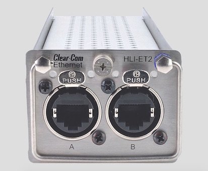
HelixNet station-to-station networking function is made possible with the HLI-ET2 Ethernet Module. Main Stations and all other Helixnet User stations can connect directly or through a LAN using conventional IT switches.
The HLI-ET2 comes standard with two RJ-45 jacks. Specifications are given below. A HLI-FBS Fiber Module is also available for linking stations over long distances. The Fiber Module has two fiber ports using small form-factor pluggable, (SFP) modules for simple exchange of fiber transceivers. The standard SFP is Single-Mode with Multi-Mode offered as an option.
Multiple intercom Main Stations may be linkable via Ethernet modules or in a daisychain configuration with optical fiber interfacing modules, enabling the summation of 12 channel or 24-channel intercom systems.
Ethernet and optical fiber interfacing modules have provision to be used concurrently in the same network. Linking HelixNet Main Stations together creates a network that pools channel resources of the individual stations. Linked main stations can dynamically discover each other thus giving HelixNet users the capability to share multiple digital partyline channels plus program inputs and any 2-wire or 4-wire interfaces in a network distributed system.
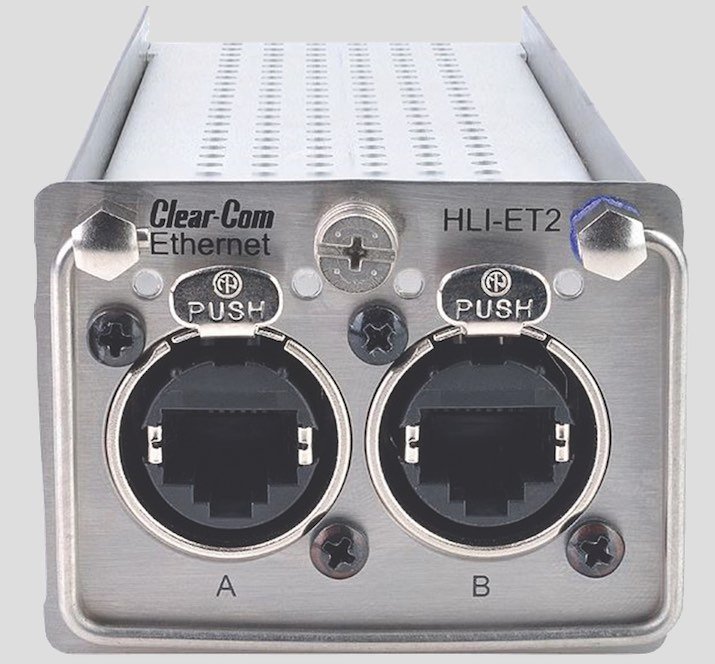
HLI-ET2
HLI-ET2 Ethernet Interface Module
The modular interface offers two Ethernet LAN network connections, enabling multiple HMS-4X HelixNet Main stations, Speaker and Remote stations to be connected.
The connection uses 10/100BaseT protocol and supports DHCP capability. Within a network the stations share all digital partyline channels, program audio signals and any or all 2-wire and/or 4-wire interface audio, and makes them available to any station or beltpack within the linked system.
All channel labels are transferred across the system automatically. The interface is equipped with two RJ-45 (Ethercon) connectors to interconnect the Main stations in to a network. The HLI-ET2 interface incorporates a rear-panel edge connector to make all the necessary audio and electrical connections and is designed to be installed into any of the HMS-4X Main station’s three module bays.
Both ports are configured to bridge traffic from one port to the other to work in a daisy-chained configuration. Spanning Tree Protocol is not enabled on these ports, therefore do not connect them both to the same network. The Ethernet interface module is able to operate with the fiber optic interface module (HLI-FBS) within the same network.
HLI-FBS
HLI-FBS Fiber Interface Module
The modular interface provides for two duplex optical fiber connections, enabling multiple HMS-4X HelixNet Main stations to be connected. The connection employs duplex single-mode and multi-mode optical fiber protocol.
Via the connection, the stations share all digital party-line, program audio signals and any or all 2-wire and/or 4-wire interface audio and make them available to any station or beltpack within the linked system. All channel labels are transferred across the system automatically.
The fiber optic interface module is able to operate with the HLI-ET2 Ethernet interface module within the same network. The HLI-FBS interface provides slots for one or two hot-pluggable SFP, (small form factor pluggable) LC duplex transceivers. The interface inserts into any of the main station’s three module bays, and has a rear-panel edge connector to make all the necessary audio and electrical connections.
Network Considerations
For HelixNet 3.0 and above, it is not necessary to be on the same Subnet. The HelixNet HMS-4X, HRM-4X, HKB-2X and HXII-BP uses a 100Mb NIC. HelixNet V3 TCP/UDP Settings Port 655 TCP – Linking HMS-4X Port 80 HTML – Core Configuration Manager Port 6000 TCP – Pairing with HKB-2X, HRM-4X, and HXII-BP Port 6001 TCP – Authenticate, update, reboot. Port 5353 UDP – mDNS, Expansion, Pair/Link
by Name, Port 6001 UDP – Audio
Managed Ethernet Switches
When connecting HelixNet to a managed network switch ensure that the network ports are set to Auto-Negotiation or 100Mb full duplex. If the system is using more than one switch the link between the switches should be set to auto-negotiation or both sides of the link should have auto-negotiation off.
One of the most common causes of performance issues on 10/100Mb Ethernet links occurs when one port on the link operates at half-duplex while the other port operates at full-duplex. This occurs when one or both ports on a link are reset and the autonegotiation process does not result in both link partners having the same configuration. It also can occur when users reconfigure one side of a link and forget to reconfigure the other side.
Unmanaged Ethernet Switches
Since unmanaged Ethernet switches do not allow user managed port speeds, it is best to use a 10/100Mb switch. If an unmanaged Ethernet switch is connected to a managed Ethernet switch, the port on the managed switch needs to be configured to 100Mb full duplex.
Hubs
Hubs should not be used with HelixNet, because when a hub receives a packet at one of its ports, it retransmits (repeats) the packet to all its ports. This means bandwidth is wasted because all traffic is sent to all ports.
IP Configuration
The HelixNet HMS-4X intercom Main Station by default sets automatic IP addressing (DHCP) enabled with menu option to disable DHCP and set static IP addresses. For this to work properly in an existing IP network there must be a DHCP server handing out IP addresses.
If no DHCP server is found, a Main Station will revert to an unused link-local address in the 169.254.0.0/16 block. A link-local address is an IP address within the local segment of any network.
Routers do not pass information to these as link-local addresses and are not guaranteed to be unique beyond a single network segment. When first connected to a network, your HelixNet device will attempt to get an IP address via Dynamic Host Configuration Protocol (DHCP). If no DHCP server is available, the unit will automatically enter linklocal IP mode. A link-local IP address will take the form: 169.254.xxx.xxx.
Note: In link-local, the address will change each time the device reboots resulting in potential loss of connection to endpoints. The units will operate in link-local, but for optimum performance it is recommended that they are used with static network settings. The preferred solution is to take a HelixNet device out of linklocal mode to disable DHCP and set static IP addresses through the Networking menu from the device front menus.
Please confirm with your network administrator that there will be no IP clashes with this address.
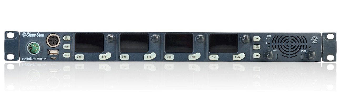
Clear-Com HMS-4X
HelixNet Network Bandwidth
HelixNet audio is 300kbps per audio stream. The total IP bandwidth usage is proportional to the number of devices connected over IP. A detailed example of bandwidth requirement calculations follows: For example, two linked HMS-4X, 10 HBP each, three HRM paired to HMS-A and five HXII-BP paired over IP to HMS B.
Pressing All Talk on HMS A sends out 1.2Mbps from HMS-A to HMS-B plus 6Mbps to 10x HBP on HMS-A, (3Mbps) & 10x HBP on HMS-B, (3Mbps) plus 1.8Mbps over IP from HMS -A (600kbps to each HRM and 600kbps to HMS-B) and 1.5Mbps from HMS-B (300kbps to each HXII-BP).
An HMS-4X to be “reachable” from where the HRM/HKB is on port 6001 (i.e. if you connect a computer where the HRM/HKB is you should be able to “ping” the HMS address or at least get a telnet connection to port 6001) can be achieved in many ways. Here are two of the more commonly utilized examples:
Scenario A
Company networks typically have multiple subnets or VLANs. IP routers are already configured to route IP traffic across those subnets. The HMS and HRM/HKB should have their IP address, Subnet mask and Gateway set properly (all automatically done when there is a DHCP server).
On the HRM/HKB deployed in a different subnet you need to Pair to Station by entering the IP address of the HMS.
HMS IP Preferences:
IP Address: 192.168.30.10
Subnet Mask: 255.255.255.0
Gateway: 192.168.30.1
HKB IP Preferences:
IP Address: 172.30.10.25
Subnet Mask: 255.255.0.0
Gateway: 172.30.10.1
Pair to Station:192.168.30.10
HRM IP Preferences:
IP Address: 172.30.10.67
Subnet Mask: 255.255.0.0
Gateway: 172.30.10.1
Pair to Station:192.168.30.10
Scenario B
The HMS is in a private/different network, not directly reachable from where the HRM/HKB is. A reachable IP router/gateway where the HMS is must be configured to forward all the IP traffic for port 6001 TCP/UDP to the HMS:
HMS IP Preferences:
IP Address: 192.168.30.10
Subnet Mask: 255.255.255.0
Gateway: 192.168.30.1
HKB IP Preferences:
IP Address: 172.30.10.25
Subnet Mask: 255.255.0.0
Gateway: 172.30.10.1
Pair to Station:69.70.166.37
HRM IP Preferences:
IP Address: 172.30.10.67
Subnet Mask: 255.255.0.0
Gateway: 172.30.10.1
Pair to Station: 69.70.166.37
Here the Router/Gateway on the HMS side must port-forward everything coming to:6001 TCP and:6001 UDP to 192.168.30.10:6001
HelixNet pairing by Name
If a HKB-2X, HRM-4X, and HXII-BP pair to a system by name, the system uses mDNS to propagate HMS and HRM presence in a network. As a device populates it’s mDNS entry, it specifies an ID, an IP address, a name and a list of services.
When configuration changes, the mDNS entry is updated and all devices connected “by name” will update and re-pair/link/expand as required.
![]()
From the November 2018 edition of CX Magazine. CX Magazine is Australia and New Zealand’s only publication dedicated to entertainment technology news and issues – available in print and online. Read all editions for free or search our archive www.cxnetwork.com.au
© CX Media
Subscribe
Published monthly since 1991, our famous AV industry magazine is free for download or pay for print. Subscribers also receive CX News, our free weekly email with the latest industry news and jobs.
Recent posts


Latest jobs