News
16 Feb 2022
Particularly peculiar potential power problems, part 2
Subscribe to CX E-News
Last month we learnt some important facts about Earth Leakage Currents (ELC) in modern entertainment systems.
Switch mode power supplies (SMPS) create earth leakage current (up to a maximum of 3.5mA per device) making them the nemesis of the RCD (Residual Current Device). An RCD is there to ensure that the circuit is protected from any leakage to earth, such as what happens when a human touches a live wire, but if you put enough switch mode power supplies on one circuit they will generate enough ELC to trip the RCD.
The amount of ELC created by a SMPS is not included on the specification sheet, so you cannot calculate how many SMPS you can connect to a single RCD without risking an ELC overload.
The 30mA rating of an RCD is the maximum trip current. This is the exact opposite of an MCB (Miniature Circuit Breaker), where a rating of 10A is the minimum current at which the breaker will trip. According to the AS3000 standard, it is acceptable for a 30mA RCD to trip with as little as 15mA of earth leakage current.
Other factors including long cable runs (particularly multicore cables) and high humidity increase the ELC in a system.
These factors add multiple layers of complexity in designing a reliable touring power distribution system.
Another factor that needs to be considered is inrush current. Both conventional and switch mode power supplies draw very large currents, typically 10-20 times the rated current, for a very short duration when power is first applied. This is usually due to the capacitors in the power supply needing to be charged. An empty capacitor is virtually a short circuit and will draw large amounts of currents for a short period of time whilst it charges. Similar issues occur when you power up filament lamps. The cold filament has a very low resistance which results in a much larger current flow until the filament warms up and the resistance rises to the normal level.
Just like fuses are available in slow-blow, normal and fast versions, MCBs are available with different trip characteristics.
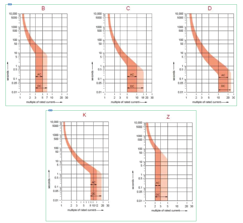
The MCB trip curves, also known as I-t tripping characteristic, consist of two sections; overload section and short circuit section. Overload section describes the trip time required for various levels of overload currents and the short circuit section describes the instantaneous trip current level of MCB.
The trip current rating is the minimum current at which the MCB will trip instantaneously. It is required that the trip current must persist for 0.1s.
https://www.electricalclassroom.com/b-c-d-k-and-z-mcb-trip-curves/
The larger the trip current the better the MCB can cope with inrush current. It seems logical then to choose the MCB with the greatest trip current rating, but the reality is very different. Nothing in life is free and MCB curves are no different. A higher trip current also means a higher overload current in general. As per the chart below, a C-curve breaker has a trip current of 10-20 times the rated current and an overload current of 5-10 times. The D curve breaker has a trip current of >20 times and an overload current of 10-20 times the rating.
The D-curve MCB is designed for motors and inductive loads and may not be suitable for protecting the electronics of a video wall or other entertainment system. Additionally, the higher overload rating may not be suitable when used with 1.5mm multicore cables, due to the risk of the cable overheating when too much current flows. The decision of what trip curve to use in a system must be made by an electrical engineer who is equipped with all the pertinent information of how the system will be used.
In Australia, almost all power distribution manufacturers use a C-curve MCB to ensure the best compromise between trip (inrush) and over current protection. Changing an MCB from the device supplied by the manufacturer and replacing it with a D-curve MCB will not only invalidate your warranty, it may also invalidate your insurance and leave you open to prosecution.
We have all seen the effect of inrush currents. You turn on a bank of 6-10 MCBs to power up a rack of audio amplifiers or LED screens and a couple of the MCBs immediately trip out. Usually, the second turn-on works perfectly but occasionally it takes 3-4 attempts before the MCB will hold. In the famous words of the late Professor Julius Sumner Miller, “Why is it so?”
It is because it all depends on the exact point of the AC waveform that you turn on the MCB. An AC voltage is a sine wave that changes from a peak of +338v to -338v and back again fifty times a second. During each cycle of the wave the voltage passes through zero twice. This is known as the zero-crossing point of the waveform. If you happen to turn on the breaker as the voltage travels through the zero-crossing point, or close to it, then the current increases slowly as the voltage ramps up towards the peak. However, if you happen to turn it on when the voltage is at the 338v peak, or close to it, then the inrush current will be at its maximum and the MCB will most likely trip. The frequency of the mains in Australia is 50Hz, and the period of a 50Hz sinewave is 20mS meaning the zero-cross occurs every 10mS. Due to the sinewave characteristic of the waveform the voltage rises rapidly from zero and the window of opportunity where the turn on voltage is low enough to prevent an inrush trip is ~2ms, making it impossible to do manually. It is only the luck of the draw that you get it right and is the reason it often takes a few attempts to get the breaker to hold. Luckily each attempt passes a short burst of current, so that the inrush is reduced on each subsequent turn on. Even if you turn on the breaker at the peak every time, by the 3rd or 4th attempt the inrush current will be low enough that the breaker will hold. Whether this rapid on/off/on/off/on cycling causes any damage to the attached equipment is an area of much online debate.
Combine this with the fact that an MCB is not designed to be used as a switch (due to the limited life expectancy – 1,000/2,000 cycles for an RCBO/MCB compared to 100,000 cycles for a switch) and it becomes clear that a better method is needed.
The same inrush problem exists for ELC as well as conventional current. SMPS will create a short peak of higher ELC at power up. Because an RCD must trip within a very short specific time (300ms for a 30mA RCD, 40ms for a 10mA RCD) this ELC inrush can be even more troublesome than conventional inrush current.
As an aside, AS/NZS 3760 stipulates that RCDs should be integral trip button tested every 6 months and injection tested every 12 months. This second test requires an RCD tester that not only applies an ELC, but also measures the time taken for the RCD to trip. If takes longer than 300mS to trip, then the RCD is deemed to have failed and should be replaced.
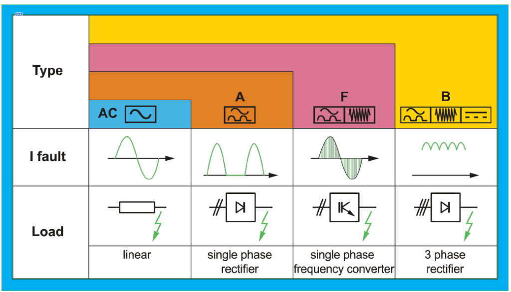
Just like MCBs have different curves, there are variations in the Types of RCD. The most common types seen in Australia are AC and A. Type AC is suitable for simple AC waveforms, but only if they are pure AC. These were commonly used in Australia until a few years ago but are not really suitable for the entertainment industry. As per the specification below, a Type A can deal with pulsating DC residual current, such as that produced by power supplies in electronic devices. Power distribution systems using Type AC RCDs may not provide adequate protection from electrocution, as the DC component may cause the RCD to not detect an earth leakage fault correctly.
Type AC
Type AC RCDs detect residual sinusoidal alternating currents. Type AC RCDs are suitable for general use and cover most of the applications in practice.
Type A
In addition to the detection characteristics of type AC RCDs, Type A RCDs detect pulsating DC residual current. Such waveforms can be caused by diode or thyristor rectifier circuit in electronic loads.
https://www.electrical-installation.org/enwiki/Types_of_RCDs
When an MCB and RCD are combined into a single device they are known as an RCBO (Residual Current Breaker with Over-current). These are now the de-facto standard in entertainment power systems since they are the same size as a standard MCB, allowing for 12 devices to easily fit into a 19” rack chassis.
RCBOs have both a Curve and Type rating. This is commonly shown as the curve letter followed by the overload current. A 10A C-curve breaker would be described as C10 and the RCD section as either Type A or just the symbol (as per the Type symbols in the diagram above). The ELC mA rating must also be shown.
It is also important to note that some states of Australia have additional rules for RCBOs. ESV (Electrical Safety Victoria) has a prohibition notice on RCBOs that have not been tested and approved by ESV. Since 2018 it has been illegal to sell a non-compliant RCBO or any product that contains a non-complaint RCBO in the state of Victoria. If a product needs an RCBO replaced it must be a compliant RCBO, even if the unit was purchased before 2018 and the remaining RCBOs are non-compliant.
In our conversations with ESV they have stated that anyone importing a device into Victoria that was built/purchased after 2018 and contains a non-compliant RCBO is liable for prosecution. This is deemed to include any production company sending equipment into Victoria for a temporary event. The complete list of compliant RCBOs is listed here https://esv.vic.gov.au/technical-information/electrical-appliances-and-equipment/compliant-rcbos/ and any production company working in Victoria should check to ensure that their products comply.
In the next instalment we will look at ELC frequency and why this makes it harder to design a reliable power distribution system.
Subscribe
Published monthly since 1991, our famous AV industry magazine is free for download or pay for print. Subscribers also receive CX News, our free weekly email with the latest industry news and jobs.
Recent posts

Latest jobs