News
11 Jul 2019
Power Over Ethernet
Subscribe to CX E-News
TECH TALK
Power Over Ethernet
by Simon Byrne.
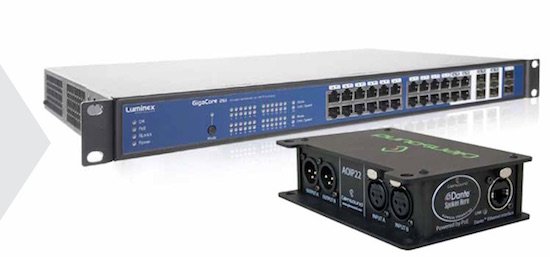
Show control systems are merging and moving onto data networks. Loosely speaking, audio, lighting and certainly video rely on TCP/IP networks of some sort. This means the devices on both ends of a link require power. This is delivered by an external power source, usually a wall-wart unless a device requires a lot, in which case the power supply is fitted internally.
So, in less power hungry devices, why are there so many wall-warts, and not internal power supplies?
In a word, compliance, which pushes up cost.
Device manufacturers are required to ensure that their widgets comply with the electrical safety and electromagnetic radiation regulations in the markets where they are sold. For products sold worldwide, this means a massive amount of work and cost is added to make the products compliant throughout the international markets.
The cost conscious solution is to outsource the power supply part of their devices which is why nearly all manufacturers buy power supplies from dedicated manufacturers, who have done the laborious compliance work.
However, if the outsourced power supply is fitted inside the widget, the widget still needs to be certified as well. This leads to external power supplies that are certified independently of the devices they power. As we all know, this leads to weak points in our systems because our high quality and expensive device is powered by a low-cost but compliant external power supply that can fall out of the outlet, combined with cheap connectors.
Our otherwise reliable solution is not looking so reliable.
It should be stated that a good regulated power supply is not hard to make. The technology is easy and proven, so the wall-warts are reliable in themselves. They rarely fail but the tendency for the wall-wart to fall out, combined with the poor connectors, is what lets them down.
If you want to learn more, read Stephen Devine’s excellent series on compliance. The link is also at the end of this article. But I digress…
For low-power network devices on Cat6 cable, Power Over Ethernet, or PoE, is a smarter solution. PoE is a nominally 48 volt DC supply voltage that is delivered using a similar concept to the phantom power on XLR that powers condenser microphones.
The DC voltage is delivered on at least two pairs of conductors of the Ethernet cable by applying a common voltage to each pair. Because twisted-pair Ethernet uses differential signalling, combined with the decent signal voltages of around five volts, the PoE does not interfere with data transmission.
There are three modes of PoE: A, B, and 4-pair. Mode A delivers power on the data pairs of 100 Mbit cable. That is, just two pairs. Mode B delivers the power on the other two, unused pairs in a 100 Mbit cable. 4-pair delivers power on all four pairs thereby doubling the amount of power that can be delivered.
For Gigabit Ethernet and faster, all four pairs are used for the data transmission, so all pairs are used to deliver power as well. Mode A has two alternate configurations (MDI and MDI-X), using the same pairs but with different polarities. In mode A, pins 1 and 2 form one side of the 48 V DC, and pins 3 and 6 form the other side.
These are the same two pairs used for data transmission in 100 Mbit circuit, allowing the provision of both power and data over only two pairs. The free polarity allows PoE to accommodate for crossover cables, patch cables and Auto MDI-X. In mode B, pins 4–5 form one side of the DC supply and pins 7–8 provide the return; these are the unused pairs in 100 Mbit. Therefore Mode B must use a 4-pair cable.
The power sourcing device (PSE), usually a network switch, not the powered device (PD), decides whether power mode A or B shall be used.
PDs that implement only mode A or mode B are disallowed by the standard.
The PSE can implement mode A or B or both. A PD indicates that it is standards-compliant by placing a 25 kΩ resistor between the powered pairs. If the PSE detects a resistance that is too high or too low (including a short circuit), no power is delivered. This protects devices that do not support PoE.
To retain power, the PD must use at least 5–10 mA for at least 60 ms at a time. If the PD goes more than 400 ms without meeting this requirement, the PSE will consider the device disconnected and, for safety reasons, remove power.
The system is quite smart. It works like this: PSE (the power source) tests PD (consumer) physically to confirm that it needs power. If the answer is yes, the PSE powers up PD. The PD sends to PSE “Hey, I’m a PD, max power needed is X, can I have max power of X”. The PSE sends to PD “I’m a PSE capable of max power X, so you can use this amount”. The PD may now use the amount of power as specified by the PSE.
The rules for this power negotiation are:
• PD shall never request more power than within the PoE specification
• PD shall never draw more than max power advertised by PSE
• PSE may deny any PD drawing more power than max allowed by PSE
• PSE shall not reduce power allocated to PD that is in use
• PSE may request reduced power, via conservation mode
As you can see, once the initial handshake is done, the power is guaranteed so it is a very stable solution.
There are two wattage standards, PoE and PoE+. PoE network switches can supply a maximum of 15.4 watts per port, and PoE+ switches can supply 30 watts per port. However, some power is always lost over the length of the cable, and more power is lost over longer cable runs.
The minimum guaranteed power available at the device is 13 watts per port for PoE, and 25 watts per port for PoE+. Designers are fully aware of these limitations and are planned for in the design of the products.
As a user though, this is another reason not to exceed the recommended 100 metre Ethernet length between devices.
Where I can, I like to over specify power supplies. This way, the components within the power supply are operating well below their specified rating, and therefore less heat is generated within those components. It is the heat within the power supplies, and its ability to dissipate the heat effectively that can cause problems.
A word about standards. The Institute of Electrical and Electronics Engineers Standards Association (IEEE) standard
for PoE is IEEE 802.3. It is important that equipment meets this standard otherwise it may not be compatible.
Some manufacturers still developed their own PoE standards after the IEEE got their act together.
Cisco in particular manufactured switches, WLAN access points, and IP phones using a proprietary form of PoE many years after the standard was issued. As late as 2014, Cisco created another non-standard PoE implementation called Universal Power over Ethernet (UPOE). UPOE can use all 4 pairs, after negotiation, to supply up to 60 W, but is not compatible with IEEE 802.3.
Why are PoE enabled switches so expensive when compared to non PoE switches? Two reasons. Firstly there are some smarts which enable the handshaking between the devices combined with the circuitry needed to apply the DV voltages where needed, and to make sure it is not applied where it is not wanted.
Also, PoE switches need quite a bit of power, so they have internal power supplies to deliver that power, which means the devices themselves need to be specified as safety compliant.
More and more networks are being combined into single larger networks. PoE enhances this by being able to deliver power over the same network infrastructure, reducing cost and increasing reliability at the same time.
We love that!
Further reading:
Compliance for Australian Entertainment Products, by Stephen Devine:
https://www.cxnetwork.com.au/compliance-for-australian-entertainment-products
CX Magazine – July 2019 Entertainment technology news and issues for Australia and New Zealand – in print and free online www.cxnetwork.com.au
© CX Media
Subscribe
Published monthly since 1991, our famous AV industry magazine is free for download or pay for print. Subscribers also receive CX News, our free weekly email with the latest industry news and jobs.
Recent posts


Latest jobs