News
28 Jul 2020
Something for nothing… Almost – Antennas
Subscribe to CX E-News
We use radio frequency links a lot on gigs. From wireless microphones, in ear monitors, crew comms, camera links, presenter remotes, wireless DMX, and nowadays, lots of people are using 4G LTE modems to stream events. All of those uses are considered critical in a show environment where even a minor failure is unacceptable.
So how do we make those links more reliable? More power is rarely the answer. Check out this example.
Say we have a wireless audio link and we want to get a hundred metres range which is twice its specified range. If we use perfectly omnidirectional antennas, known as an isotropic on both ends of a radio link, and we want the link to travel twice as far by using power only, you’d think that you need twice the power, right? Unfortunately not. That won’t work because it is not a 1:1 ratio, you actually need about ten times the power! That is because the inverse square law applies and twice the power only gets you about forty percent more range.
The other downside to more power using isotropic antennas is potential interference with other devices because we are pushing out a lot of power in all directions. Not good. However, by using smart antenna design, the amount of power is dramatically reduced.
Before I go further, we need to revisit decibels with reference to power, which is calculated differently to decibels in reference to sound pressure level. With power, an increase of 3 dB is double, 6 dB is four times, 10 dB is ten times, and 20 dB is one hundred times the power. With SPL, a 6dB increase is double because the base of the logarithm is twenty.
Isotropic antennas are really only theoretical. They are the perfect idealised omnidirectional antenna that do not exist in real life. They are however our reference point for antenna gain. Now importantly when we talk of gain in antennas, we are not talking of gain where an amplifier is involved.
With antennas, gain is in reference to our theoretical perfect isotropic antenna and defines the degree to which an antenna concentrates radiated power in a given direction. That is, instead of radiating the power omnidirectionally, the power is focussed in a given direction, thereby radiating more power in that direction. That of course means that an antenna has to be poorer in the other directions.
Now, if we have a directional antenna on just the receiver alone of our example above with a gain of 10 dBi (10 decibels of gain when referenced to our isotropic), we have solved the problem without extra power because the receiver is now pulling in ten times the power from a single direction.
Now imagine if we had a directional antenna on the transmitter too which also had a gain of 10 dBi bringing the total gain in the system to 20 dBi. As long as you have line of sight, we now have a link capable of five hundred metres! This is because we have increased the gain by one hundred times.
By way of background, the International Space Station has a standard Kenwood D700 amateur radio with a transmission power of just 5 watts on 145.8 Mhz. The ISS is 408 kilometres above the Earth, yet ham radio enthusiasts routinely establish dialogue. The key is great antennas!
Radio waves are a type of electromagnetic radiation with wavelengths. The wavelength of radio waves can be anywhere from millimetres to many thousands of kilometres. Like all other electromagnetic waves, radio waves travel at the speed of light in a vacuum and the wavelength for radio signals can be calculated by dividing the speed of light by frequency.
To receive radio waves, you need an antenna of some sort which electrically resonates to the frequency.
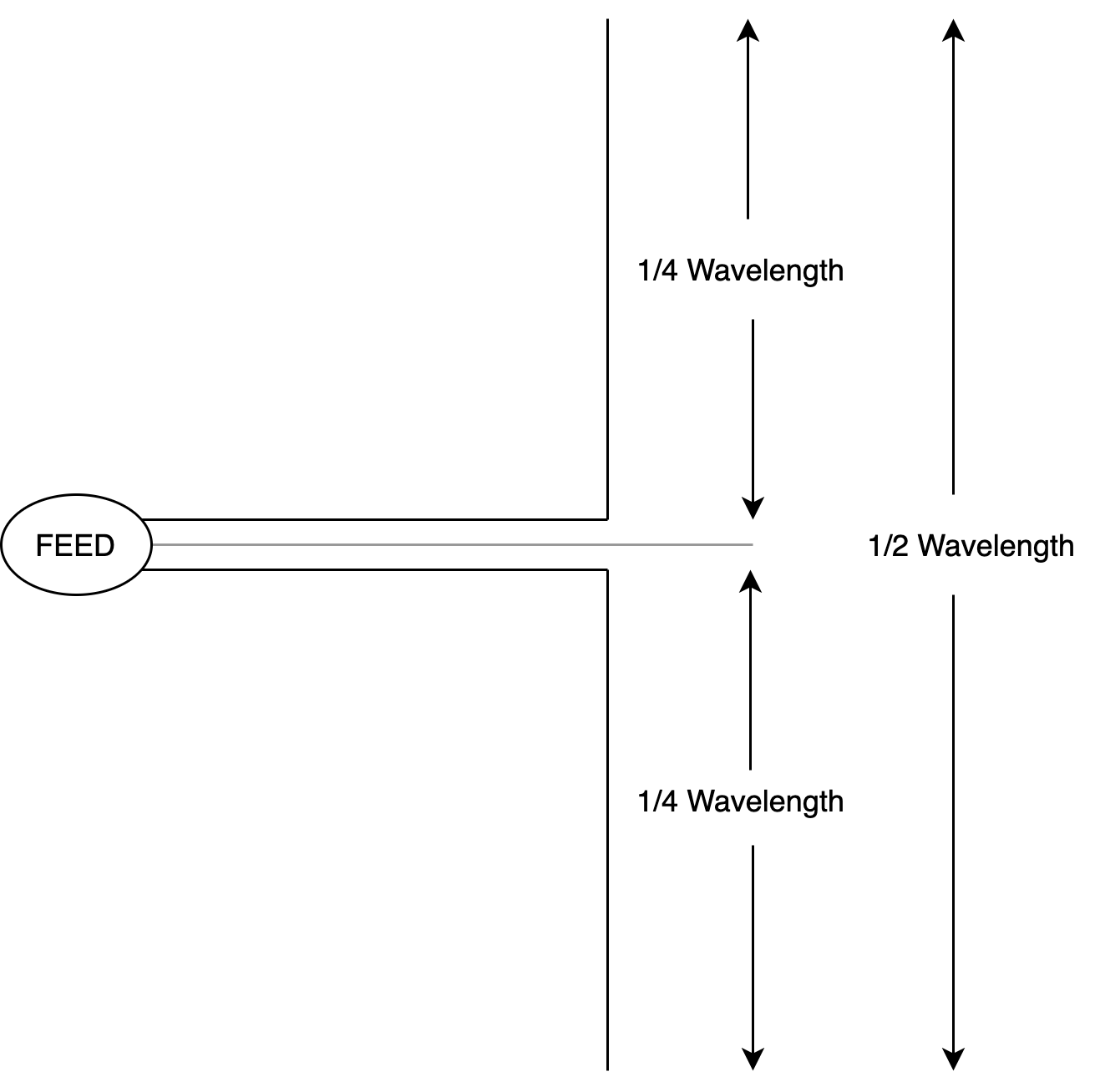
The 1/2 wave dipole
In real life, the fundamental antenna is the 1/2 wave dipole. The 1/2 wave dipole is made up of two 1/4 wave conductors. For example, the wavelength of 600 Mhz from a wireless microphone is five hundred millimetres. Therefore, a dipole will be made up of two 1/4 wave conductors 125 mm long.
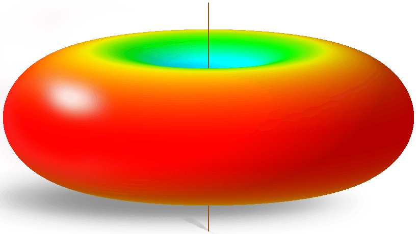
Why not a full wave antenna? If you think about it carefully, a full wave antenna will not work because both the positive and negative portions of the wave are being presented to the antenna at the same time, so it cancels itself out. Say our 1/2 wave dipole is oriented vertically, it is said to be vertically polarised. It will pick up vertically polarised signal from all directions around it horizontally, but not so well from directions above and below it. This is because its reception is like a doughnut.
These antennas are considered omnidirectional in the real world and 1/2 wave dipoles have a gain of just over 2 dBi. Most other antennas are derivatives of the dipole. Designers can do some clever beam shaping by using multiple omnidirectional antennas and manipulating the phase of the signals on those multiple antennas.
The 1/4 wave monopole
The 1/4 wave monopole is really just the top half of a dipole, referenced to a ground plane. You see these everywhere as they are the cheapest, simplest antennas to deploy. For example, many lower end wireless microphone receivers often come with 1/4 wave antennas. A 1/4 wave antenna must always have a ground plane. That is, something for it to work off. For example, in wireless microphone receivers, the case of the receiver itself (which could be considered the other half of a dipole).
As long as you have a really good ground plane (you rarely do), theoretically you can get as much as 5 dBi gain because the ground plane tends to focus the energy into the 1/4 wave. In the real world however, a good ground plane on portable is rare, so the gain is usually much less. It is for this reason that separating a 1/4 wave antenna from its device with a cable in between is usually a bad idea.
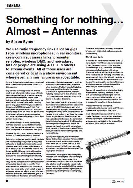
The Yagi
Yagi antennas are made using a 1/2 wave dipole with other elements to direct and reflect the waves. A typical Yagi antenna has one element behind the dipole. This element is called a reflector. The reflector is slightly longer than 1/2 wavelength. The elements in front of the dipole are called directors.
The practical gain of Yagi antennas is 6 to 20 dBi, depending on the number of elements. As a consequence of its ability to provide high antenna gain on a tuned frequency range, the Yagi antenna is not good for picking up a wide range of frequencies which is needed for a wide band system such as a wireless microphone system which can operate from say, 520 Mhz to 694 Mhz.
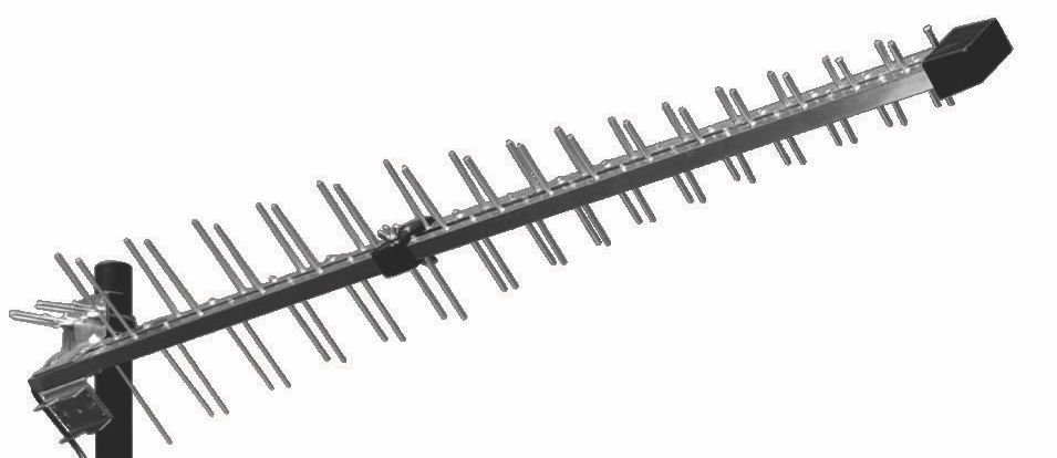
The LPDA
The solution to the bandwidth problem is a log periodic directional array, sometimes known as an LPDA. They look similar to, and are often confused with, Yagis. LPDAs are directional antennas that can resonate over a wide range of frequencies.
All they are is an array of carefully spaced dipoles, sized to resonate at the different frequencies within the required range. Depending on the frequency being picked up, the matched dipole acts as an antenna, and the others act as directors and reflectors. Super clever!
A typical LPDA has a gain of 7.5 to 9 dBi across a wide bandwidth. That is an increase of nearly ten times the power which is very respectable. Paddle antennas are LPDAs.
Cable
Don’t throw away your gains with poor cable! It is important to note that a lot of power is lost in the antenna cable and you must plan for it. Generally speaking, the higher the frequency, the greater the loss. Using the classic RG58 coaxial cable at 600 Mhz, you’ll lose 3.8 dB over a ten metre length. But using the more expensive LMR400 coax, you only lose 1 dB over ten metres.
Losses in cable can be overcome by using as shorter lengths as possible, or with radio frequency amplifiers. For example, Shure’s range of paddles have switchable RF amplifiers built into them, solely to overcome cable and connector losses.
It should be noted that terminating good RF cables can be quite tricky. There is a lot of voodoo to how RF works within a cable because you want maximum power transfer within the cable without reflections. The power does not travel within the conductors. Instead the electromagnetic field exists between the inner and outer conductors so spacing and design is of utmost importance.
For critical RF cables, I get RF specialists to make cables for me, usually out of LMR400 with quality connectors. By quality connectors, I mean a brand that has been tested in a lab and proven to perform. A lot of the copies may look exactly the same, but quite often their performance is very poor.
As well as high performance antennas, there are lots of other things you can do to improve wireless links.
Line of sight. Duh! No wireless link should be considered reliable on a show unless there is line of sight between the transmitter and receiver.
Get them up high and pointing correctly. By getting at least one end up high, you are obviously removing signal path obstructions, but also reducing the strength of any multipath reflections from the ground because they have to travel much further as a result of the greater distance and angle of the antenna from the ground.
Talking of multipath reflections, they are always there because there is always at least one other RF reflective surface, the ground you are standing on. In addition to the the ground reflections, there are usually walls, steel rigging, vehicles etc which all reflect radio waves. They can meet at the receive antenna in a constructive way, in that they add to each other which is good. Or they can combine destructively, which is bad.
This is why diversity reception exists. Say you had a one in one hundred chance of a dropout as a result of a multipath signal combining with the direct signal destructively at the receiving antenna. On a gig, that is not good enough. However, add another antenna and receiver that is physically uncorrelated to the first which also has a one in one hundred chance of a dropout.
What is the chance that they’ll both dropout at the same time? One in two hundred perhaps? Or is it more? In theory, it is one in ten thousand because you multiply the probabilities. This is obviously why diversity receivers are so popular, but for the diversity to really work, they must be genuinely uncorrelated. That is, picking up the signal independently.
To do this, your diversity antennas must be spaced by a large multiple of your wavelength. In our 600 Mhz example, the wavelength is half a metre, so as long as your spacing is more than that, and up high, you are good to go.
What about two antennas connected together in parallel to a single input on a receiver? This does not work because they can work against each other. You can have an out-of-phase signal being received which cancels out an otherwise good signal from the other antenna.
4G LTE
A lot of us are now streaming events using 4G LTE modem dongles. In Australia, 4G networks use seven different frequency bands, ranging from 700Mhz (known as Band 28) through to 2600Mhz (Band 7).
As a user, you have zero control as to what band is provided to you by the network. That is a shame because the band that you connect to really affects your speed. The higher frequency bands tend to deliver greater speeds, but with much less reach, and the lower 700Mhz frequency is great too because it tends to get around obstructions much better, albeit with less upload/download speed.
Because of these wide range of frequencies, your modem dongles need very wideband antennas. This is no easy feat as the wavelengths range from 11.5 centimetres up to 43 centimetres, and the modem dongles normally have the antennas built into them. Then, as the modem is usually indoors, we lose transmission power through the walls, have to deal with multipath reflections, and so on.
And lastly, our modems may have to compete with the interference generated by every other mobile phone in the room, as well as any other users between the venue and the cell tower. It is impressive that they work at all!
The network cells are spaced roughly three kilometres apart. In sparsely populated areas they are spaced further apart and will tend to use the lower frequency bands as the lower frequencies propagate further. In densely populated areas, there are many more cells spaced more closely. This is so the telcos can use the available spectrum more efficiently by using lower power transmissions which gives the telcos more capacity, plus there are many more obstructions in populated areas.
More smaller cells in an area equals more users.
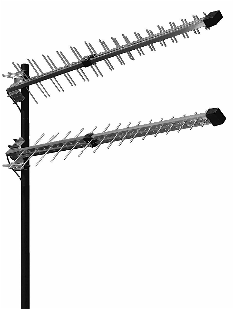
4G LTE can use multiple frequencies and may switch at any time. It is done as part of a technology called MIMO. Multiple In, Multiple Out works by using at least two antennas and transceivers on both ends (known as 2 by 2).
It is an extremely sophisticated version of diversity that takes advantage of the polarisation angle and phase of both signals to extract out more capacity. In MIMO, one channel is polarised at +45° from vertical, and the other is at -45°. That is, 90° apart which gives it diversity separation. MIMO configured antennas are easy to spot because of this.
So how do you get a reliable signal? External, well designed antennas, in a MIMO configuration. Many modem dongles have two connectors for external antenna. They’ll instantly give you about 4 dBi, but if you are able to put them outside, you can get as much as a 20 dBi increase. That is one hundred times more power getting out of your modem dongles to the cell! I regularly get 40 Mbps upload speed with my 2 by 2 external MIMO antennas, whereas indoors I usually only get about 9 Mbps upload using the internal antennas.
If you want to know which band your cell tower has assigned to you, most modem dongles can display that information by way of their diagnostics page using a web browser. In these pages, you can get a whole heap of other information too.
RSRP and RSRQ are the two important indicators of signal strength and quality. RSRP stands for Reference Signal Received Power and RSRQ stands for Reference Signal Received Quality. These two indicators combine to give you a very good picture of what is going on with your connection. You can have a low strength connection, but still good quality. Normally though they go hand in hand.
| 4G LTE Power and Quality | RSRP (dBm) | RSRQ |
| Excellent | Less than -80 | Less than -10 |
| Good | -80 to -90 | -10 to -15 |
| Mid Cell | -90 to-100 | -15 to -20 |
| Cell Edge | Greater than -100 | Greater than-20 |
There is another indicator, RSSI which is Received Signal Strength Indicator. This is the one that gives you the bars on your phone. It is however quite a poor indicator of what is really going on because it is showing the received power across all the LTE bands, not just the ones you are using.
For this article, I’ve stayed away from 5G because its coverage is still patchy. However, it is a spectacular set of technologies that operates at much higher frequencies and may use as many as 128 MIMO antennas to achieve very sophisticated beam steering. As a result of the very high frequencies, the telcos need many more low power base stations to achieve the same coverage.
Get to know your local RF specialists. These are the guys who sell commercial two-way radios, repeaters, point-to-point data links, properly designed MIMO antennas for 4G LTE, and so on. They are a wealth of information as they live RF theory, plus they have the quality cable by the metre as well as the connectors that work properly.
In my experience, they really enjoy working on our projects as well. Now for you grammar police, I’m aware that many of you think the plural of antenna is antennae, not antennas. But when researching this piece, most of the RF engineers refer to them as antennas, and so have I.
CX Magazine – July 2020
LIGHTING | AUDIO | VIDEO | STAGING | INTEGRATION
Entertainment technology news and issues for Australia and New Zealand
– in print and free online www.cxnetwork.com.au
© VCS Creative Publishing
Subscribe
Published monthly since 1991, our famous AV industry magazine is free for download or pay for print. Subscribers also receive CX News, our free weekly email with the latest industry news and jobs.
Recent posts


Latest jobs