News
28 Mar 2022
The Problems with Power, Part 3
Subscribe to CX E-News
In the first two articles of this series, we looked at the problems that can cause unexpected circuit breaker tripping in a power distribution unit (a.k.a. Distro or PDU). We discovered that the ubiquitous Switchmode Power Supplies (SMPS) that are used inside almost everything, create Earth Leakage Current (ELC), up to 5mA per device! We also learnt that a Residual Current Device (RCD) with a 30mA rating actually trips anywhere from 15 to 30mA. Finally, we learnt about in-rush currents, both conventional and earth leakage, and how these relate to the way we power up our rigs. When all these facts are combined, it is no wonder that there are problems.
In this instalment we will look at how one seemingly innocuous device, commonly used in many lower cost PDUs, may cause untold damage to anything connected to that distro. Then we will look into ELC frequency and how that makes it much harder to measure the ELC in a system, and finally we look at ways to mitigate both of these and the other issues we have discovered along our journey.
Beware the 4-pole switch
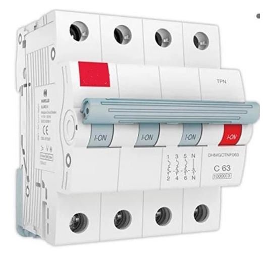
Many power distribution products now include a ‘master switch’ that allows the operator to easily turn on/off all the channels in a distro rack without needing to use the individual MCB/RCD protection devices. This is a great idea due to the previously mentioned issue of the low mechanical service life of an MCB/RCD (2,000/1,000 cycles) compared to the long mechanical life of a switch (100,000 cycles).
Recently though, we have heard a few operators using low-cost imported distros report issues of massive overvoltage events, destroying a third or more of the downstream connected devices when operating these master switches. One hire company returned a batch of DMX splitters to us, all of which had received a blast of 440v to the power supply.
The cause of this is the use of an incorrect (cheaper) type of 4-pole switch. The reason to use a 4-pole over a 3-pole device is due to OH&S, as the 4-pole unit disconnects not just the 3 active phase wires, but also the neutral feed. This is critical to protect users from electrocution if there is a phase-neutral wiring fault in the upstream power outlet to which the power distro is connected. If there is voltage on the neutral line, then a 3-pole device will not disconnect this feed, whereas a 4-pole device will ensure that there is no voltage on any downstream device.
However not all 4-pole devices are created equal!
It is critical that you use an MFBL 4-pole switch. MFBL is an acronym for Make First, Break Last. Without this feature things can go bang very quickly when the power is switching on or off.
What is MFBL? If you look at a standard Australian 3-pin plug, you will notice that the earth pin is longer than the active and neutral pins. This is to ensure that earth connection Makes First when the plug is pushed into the socket and Breaks Last when it is removed. This ensures that the earth connection is connected before any voltage is connected. Without this feature a plug that is loose in the socket could potentially have active and neutral connected but no earth connection. By making the earth pin longer it becomes impossible to insert or remove the plug in a way that connects the hot pins without the earth first connecting.
An MFBL 4-pole switch does the same for the Neutral. It makes sure that the Neutral is connected first, followed by the three phases. It does the opposite when turned off, disconnecting the phases first, then the neutral last. If you use a non MFBL 4-pole switch then it is possible that when you turn the switch on/off, the Neutral line may break first or make last, leaving the three phases connected without a neutral.
Why is this a problem? Unlike a single-phase plug, where you need both the active and neutral wires to be connected before 240v flows, in a 3-phase system, voltage can flow with any two or more of the four wires connected. If the neutral is not one of the connected wires, the system will go out of balance and the voltages on the phases can reach 415v. Most electrical devices will fail (expensively) within milliseconds of such a high voltage. Imagine that happening as you power up the rig for the final day of a festival or corporate event.
This is the same damage that occurs if you are unlucky enough to have a neutral failure at a gig. A short firework and smoke show is followed by an eerie silence and darkness, then large amounts of cursing from the owner of the damaged equipment. Lesser damage can occur with what is known as a soft neutral, where the cable overheats and can no longer carry the required current, causing the phase voltages to drift above or below the normal operating range of the attached equipment.
Mitigation of this issue is relatively easy. Most advanced power distribution systems provide dropped Neutral and/or over-voltage protection. Of course, not all systems are created equal, and some systems work better than others. Make sure you do your homework on how they work and, critically, how long they take to trip. It is no use having a system that takes >100mS to disconnect the power if your equipment fails within 50mS.
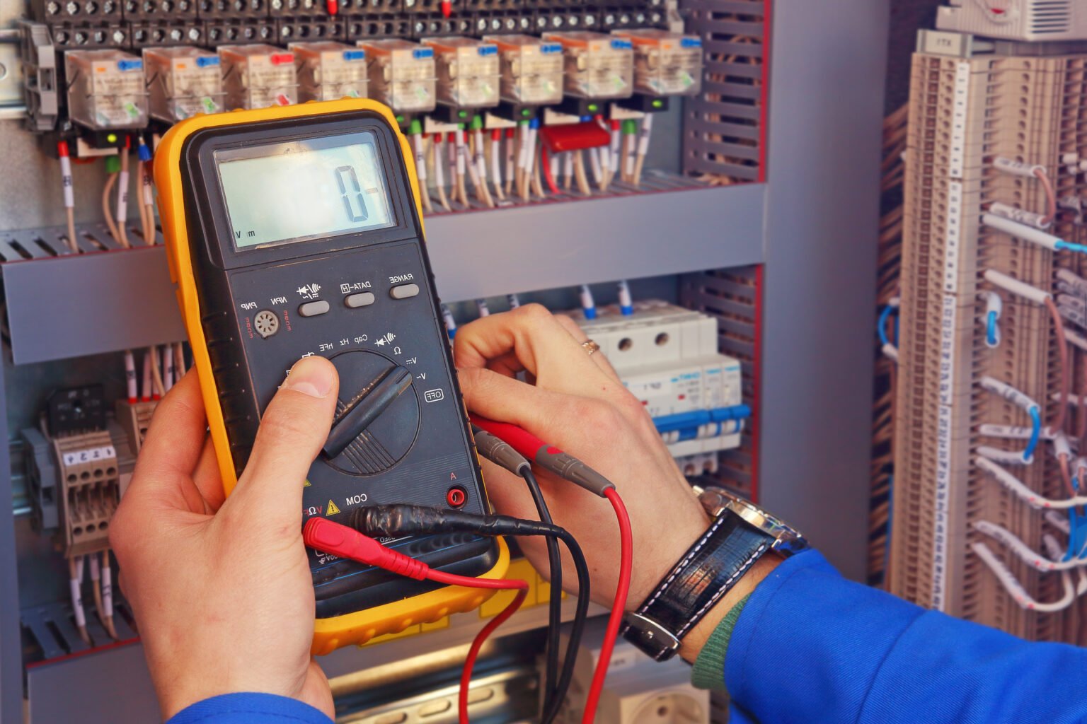
Pitfalls when measuring Earth Leakage Currents
Reducing the risk of nuisance ELC tripping is much harder, particularly when it comes to measuring the ELC in a device or system. During our research into ELC and the nuisance tripping of RCDs we made the unexpected discovery that it is not possible to accurately measure the ELC of a device by using a standard current clamp or multi-meter. One of our test rigs used a popular 1200w moving light with electronic ballast. We measured the ELC using two different calibrated meters, each with 0.1mA resolution. During normal operation both meters showed ~20mA of earth leakage current. Imagine our surprise when we were able to run four of these units with a measured 74mA of ELC on a 30mA RCD without it tripping. Once the engineers connected the oscilloscope the answer was obvious – harmonics. An electronic ballast produces large amounts of ELC but most of it is not at 50Hz, the vast majority is in the harmonics, at 150Hz or above.
The problem is that RCDs are designed to work with mains frequencies, which are 50/60Hz. They effectively have a 100Hz low pass filter built in. If we want to know how many devices
can be connected to a single RCD we need to measure the ELC with the same parameters as the RCD reacts to, otherwise the harmonics will give us a meaningless reading. Standard current clamp and multi-meters cannot do this task. The solution is to buy a proper dedicated ELC meter. The Kyoritsu brand seems to be the de-facto standard but expect to pay over $1,000 for one of their little toys. It also needs to be regularly calibrated to give accurate readings.
If you just use a multi-meter and measure 4mA per device, you may decide that you can only safely connect 3-4 units per circuit. If most of this ELC is in the harmonics, then the ELC at 50Hz may only be 1.5mA, meaning you could reliably connect nine units per circuit and still remain below 15mA. The difference in labour, cabling and number of distro circuits required in these two scenarios may be the difference between winning and losing the bid for the gig.
You also can’t just measure one example of a device and expect all the other units to have the same ELC. Each SMPS has tolerances that will affect the amount of ELC generated. Good quality power supplies will be +/- 10%, or less, but cheap SMPS can vary by far larger amounts. The only way to be sure is to measure and label every single item in your inventory and label them accordingly. Then you can simply add the numbers together every time you put a rig together.
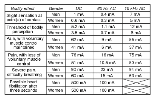
As an aside, this realisation that RCDs only respond to 50/60Hz led us to ask what effect does the frequency of the current have with regards to the protection of human life? Can I still be electrocuted by 40mA of ELC if it is mostly high frequency harmonics? There has been much scientific research into the topic and it turns out that as the frequency of the current increases, the effect on the human body reduces. This seems to support that argument that the limited frequency response of the RCDs is not of major concern. It was also interesting to note the differences between both AC and DC voltage as well as male/female subjects in regard to the effects of electricity on the human body.
Mitigation
In summary, here are a few rules to follow that will help you avoid the issues that have been discussed in this series of articles.
1. Never use a breaker (MCB, RCD or RCBO) as a switch. The short service life (1,000-2,000 cycles) of an MCB/RCD compared to the 100,000 cycles of a dedicated switch will result in increased maintenance costs as well as increasing the risk of trips due to ‘soft breakers’.
2. Always turn on one outlet of a power distro at a time, to reduce in-rush to any up-stream breaker. Turning on 12+ circuits in a single hit (e.g. when using a master switch) could result in an in-rush current that trips the upstream feed breaker. Do you know where that is? Do you have a key to the room/cabinet?
3. Always turn on outlets at the zero-cross point of the AC waveform. This one is a bit tricky for mere mortals, as the zero-cross point is only a few microseconds long and occurs every 10mS. A microprocessor controlled PDU may provide this ability.
4. Measure the ELC per circuit and re-measure when changing cable infrastructure (adding a multicore) and as weather conditions change. Don’t use a standard clamp or multi meter. Make sure you have a proper, calibrated ELC meter that has the correct low-pass filter that matches that of an operational RCD. The Kyoritsu brand seems to be the most popular.
5. Use a ‘ramping’ RCD tester to measure the tripping point of each RCD/RCBO in your system, then label them accordingly. A ramping tester slowly increases the ELC in 1-2mA steps and then records the value at which the RCD trips. Again, Kyoritsu are the go-to brand for these devices.
6. Use the information gathered in (4) & (5) to ensure that your ELC flow is lower than the RCD trip point. These calculations need to be done for every channel. Don’t forget to add a margin for error.
7. Ensure any 4-pole switches and/or breakers are MFBL. Make First, Break Last devices ensure that the Neutral is always connected whenever a phase voltage is connected and ensures that the phase voltage/s always has the correct neutral reference.
8. Ensure your power distro uses C-curve circuit breakers. These are generally considered to be the safest option for our industry and provide excellent protection from in-rush tripping if you follow (3) above.
9. Ensure your power distro has dropped neutral protection. This is probably the cheapest insurance you can buy if you do production hire. Almost everyone I talk to has heard a horror story of a dropped neutral at a gig.
10. If your power distro uses compact RCBO’s (most do) and you work in Victoria, make sure they are approved by Electrical Safety Victoria (ESV).
You can check if your RCBOs are legal in Victoria via this weblink.
https://esv.vic.gov.au/technical-information/electrical-appliances-and-equipment/compliant-rcbos/
In the next (and final) instalment we will look at the LSC power distribution range and the technologies developed to address all of these issues.
Further Reading
These two articles explain what happens when the human body receives an electric shock.
https://www.electrical4u.net/why-question/electric-shock-how-does-human-body-get-electric-shock/ https://jmkengineering.com/electric-shock-human-body
Subscribe
Published monthly since 1991, our famous AV industry magazine is free for download or pay for print. Subscribers also receive CX News, our free weekly email with the latest industry news and jobs.
Recent posts


Latest jobs
